Introduction
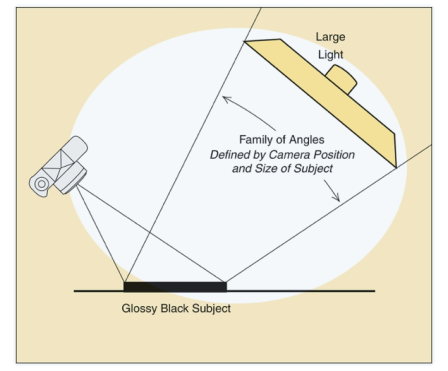
Hunter et al (2012, p39) tells us that the direct reflection is produced when a light is directed at a polished surface, such as metal or glass. The rays bounce from points on the smooth surface at the same angle as which they hit it. Therefore the angle of incidence equals the angle of reflection. They continue by explaining that the family of angles (FoA) is the area formed by a collection of these ‘bounce’ points.
However, when reading chapter 6 of Light-Science and Magic I came across an exercise (p121) that is designed to help identify where the FoA might lie when lighting metal. I decided to carry out the exercise and see what could be learned.
Finding the Family of Angles
I placed a metal garlic press on a black fabric background. I placed the camera onto a tripod set the lens to 55mm and pointed it down towards the subject at an angle of approximately 40-45 degrees.
1. Position a white target where you think the family of angles will be
The white target could be any convenient diffusion surface. The less sure you are of where the FoA lies the bigger the surface should be. As I had very little idea about where the FoA lay I chose a 106cm diameter diffusion panel. I placed it behind the subject.
2. Place a test light at the camera lens.
This light is a called a ‘test’ to distinguish it from whatever light we eventually use to make the picture. As the beam of the light had to be narrow I opted to use a small torch. This torch’s beam had to be in line with the camera lens so I removed the camera from the tripod and taped the flashlight to the top of the tripod.
3. Aim the test light.
I aimed the test light at the point on the garlic press that was closest to tripod. The idea was that the light would reflect off of the metal and onto the white target sheet. However I couldn’t see the light reflected in the diffusion sheet at all. I wondered where I had gone wrong and mentally retraced the steps. I decided to play around with the position of the white target. I placed it directly overhead, no test light to be seen. I tried positioning it more to one side but this didn’t seem to be catching the metal reflections either. It seems I had totally misjudged the family of angles. However, when I placed the diffusion sheet back behind the subject but angled I had a bit of a eureka moment when the saw a light reflected in the sheet to show the near limit of the FoA. I marked this spot with a piece of removable tape as instructed. I repeated this by moving the flashlight to farthest point on the metal and marked the far limit of the FoA with tape too. I shone the light on a few other points but these reflections did not extend beyond the near and far limit of the FoA I have previously marked.
4. Study the position and shape on the area marked on the white target.
The area marked was very low down on the white target and fairly narrow in width. It was interesting to note that the point reflecting in the bottom of the image corresponds to the limit marked at the top of the test surface and vice versa. Hunter et al (2012, p124) notes that being aware of this is useful in locating the source of glare and hotspots in future set ups.
How to light the metal
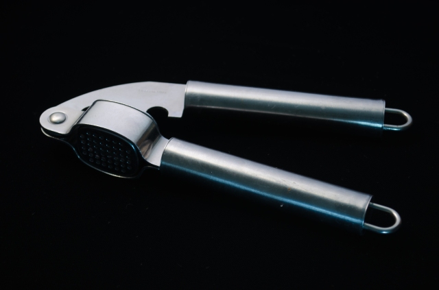
So it seems that after a bit of trial and error I had succeeded in finding the FoA. Now how should I light it. Hunter et al (2012, p125) notes that to keep the metal bright the light should at least fill the FoA to produce direct reflection. After removing the torch and replacing the camera onto the tripod I placed a spotlight behind the diffusion sheet. I took some time adjusting the distance until the light more than filled the FoA that I had identified.
Dark
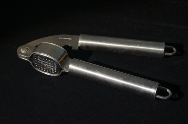
To make the metal look dark Hunter et al (2012, p128) note that the light can be positioned anywhere outside the family of angles therefore avoiding direct refection. I positioned the light near the camera and took this shot.
The metal is indeed darker than in the first shot and has less areas of bright highlight which allows some more details to be seen. It does seem quite dull though.
Conclusions
This exercise has helped illustrate in a very hands-on way that the FoA behaves for direct reflection, relative to the light source, camera and position of the subject. It has demystified the concept for me (somewhat) by demonstrating how, once the FoA are located, they can be managed to show or not show reflections. It would seem though from my two examples above that a middle ground between keeping the metal bright and dark might be a better outcome for some subjects. Hunter et al (2012, p131) describe lighting set-ups that fill the FoA to produce direct reflection from the metal plus illuminate from other angles to produce diffuse reflection from the background as an Elegant Compromise.
Hunter, F., Biver, S. and Fuqua, P. (2012) Light-Science and Magic (4th Ed.) Waltham, Focal Press


